Introduction
A well screen is a filtering device that serves as the intake portion of wells constructed in unconsolidated or semi-consolidated aquifers. The screen permits water to enter the well from the saturated aquifer, prevents sediment from entering the well, and serves structurally to support the aquifer material. The importance of a proper well screen cannot be overemphasized when considering the efficiency of a well and the log-term cost to its owner.
Well screens are manufactured from a variety of materials and range from crude hand made contrivances to highly efficient and long-life models made on machines. The value of a screen depends on how effectively it contributes to the success of a well. Important screen criteria and functions include:
Criteria:
- large percentage of open area
- non clogging slots
- resistant to corrosion
- sufficient column and collapse strength Functions:
- easily developed
- minimal incrusting tendency
- low head loss through the screen
- control sand pumping in all types of aquifers
Continuous-Slot Screen
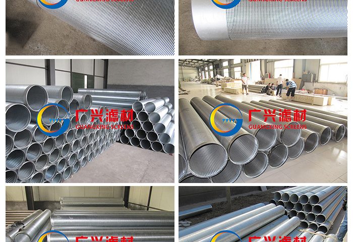
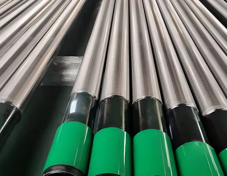
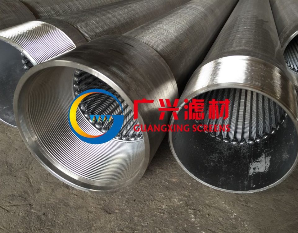
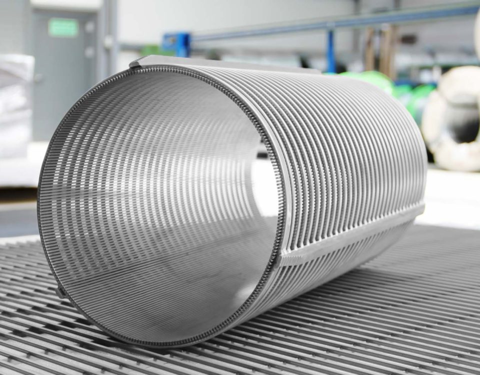
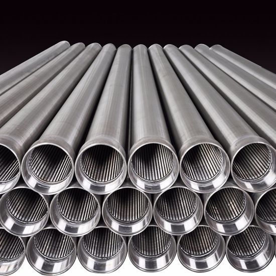
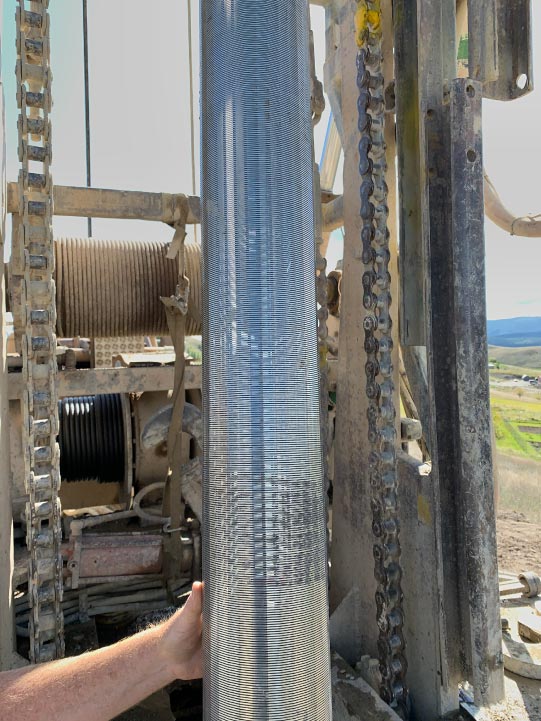
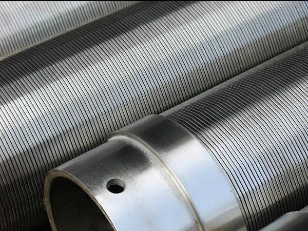
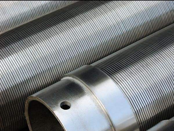
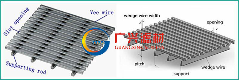
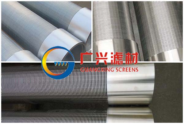
The continuous-slot screen is widely used throughout the world for water, oil, and gas wells, and is the dominant screen type used in the water well industry. It is made by winding rolled wire, triangular in cross section, around a circular array of longitudinal rods. The wire is attached to the rods by welding. Welded screens are commonly fabricated from stainless steel.
Slot openings are manufactured by spacing successive turns of the outer wire to produce the desired slot size. Slot openings have been designated by numbers which correspond to the width of the openings in thousandths of an inch. A No. 10 slot screen, for example, is an opening of 0.〇1〇 inch.
Continuous-slot screens provide more intake area per unit area of screen surface than any other type. This type of screen has maximum open area. For best well efficiency, the percentage of open area in a screen should be the same as, or great than, the average porosity of the aquifer material. Water flows more freely through a screen with a large intake area compare to one with limited open area. The entrance velocity is low, therefore head loss for the screen is at a minimum, thus minimizing drawdown in the well.
Well Points
Well points are made of a variety of types and sizes. The welded continuous slot screen is made as a well point by attached a forged-steel point to the lower end of a screen and a threaded pipe shank to the upper end. This type of construction is the most efficient hydraulically. The most common sizes are 1 % inch or 2 inch. They are constructed of either low-carbon steel or stainless steel. Although they can withstand hard driving, they should not be twisted while being driven or used in areas where boulders or large stones are expected.
Screen Installation
There are different types of screen installation methods used, although certain procedures may be more practical or more economical in certain areas or when particular drilling rigs are used. The exact procedures to be followed when installing a well screen depend on
the nature of the aquifer materials, the method used to drill the well, the dimensions of the borehole, the hydraulic conditions in the aquifer, and the casing and screen materials.
Other Types of Well Screens
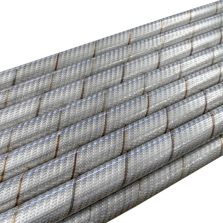
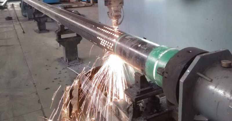
Several other types of well screen exist. Some are manufactured and others are hand perforated from casing or other materials. These screens may be adequate in some geologic formations, but may provide only marginal success under many other hydrogeological conditions. Limited open area, poor slot configuration, and short-lived screen material contribute to their limited success.
Slotted Plastic Pipe
Slotted plastic pipe is also use to screen wells in some areas particularily in clay rich soils where no aquifer zone can be identified. Slotted plastic screens are not affected by corrosive water, are easy to install, and are relatively inexpensive. Slotted plastic screens have less than half the open are of continuous-slot screens. In addition, plastic pipe materials are from 1/6 to 1/10 as strong as stainless steel well screens.
Pull-Back Method
The pull-back method of screen installation is a safe method of installation that reduces problems resulting from heaving sediment, sloughing of the borehole walls, and setting the screen at the wrong depth. This method also permits the screen to be removed and replaced, if necessary without disturbing the sanitary grout seal outside the well casing.
The pull-back method involves installing the casing to the full depth of the well, lowering (telescoping) the well screen inside the casing, and then pulling back or lifting the casing far enough to expose the screen to the water-bearing formations. The casing must be strong enough to be set the full depth of the well and then be pulled back the length of the screen.
Some contractors use a rise pipe (blank) attached to the top of the screen so the entire screen can be exposed without slipping out of the bottom of the casing. On top of the screen, a neoprene packer is installed to provide a sand-tight seal between the top of the screen and the casing. Two or more packers are used in series to eliminate problems caused by small deviations in the dimensions of the casing or packer resulting from improper handling.
Single String Installation
Sometimes the screens are attached directly to the bottom of the casing. Screens that are smaller in diameter than the casing can be welded or threaded directly to the casing by mounting a cone adaptor or flared weld ring to the top of the screen. Screens that are the same size as the casing can be welded or threaded directly to the bottom of the casing. The casing and screen are then set in the hole. For naturally developed wells, the formation is induced to cave in around the screen and casing immediately after the screen is set. When wells are filter packed, the pack material is placed before the formation is induced to cave.
Slot Size & Sieve Analysis
Slot size selection is a critical step in assuring maximum well performance. The screen is typically designed to hold back 50 percent of the formation, and the entrance velocity of the screen should not exceed 1/10 or .1 foot per second. The velocity is calculated by dividing the well yield in gpm by the screen open area in square inches.
The slot size of the screen is based on a size analysis of the formation samples. By analyzing the component sizes of the grains in the sample, a grain-size distribution curve can be drawn. Several methods can be used to obtain information on the grain size distribution. The most widely used method involves passing the materials through a stacked set of brass or stainless steel sieves.
During the sieving process, each sieve filters out a certain percentage of the entire sample; the finest material collects in the bottom pan. Sieve analysis not only provides the basis for determining the slot size, but also other factors affecting screened well design. Sieve analysis is also used for filter pack design.
Filter Packed Wells
Many wells are designed for a filter pack, thereby altering the screen installation process. Filter-packed wells different from naturally developed wells in that a silica sand is placed around the well screen to a predetermined thickness. The geologic conditions, drilling method, and type of screen determine whether a filter pack should be used.
The filter pack provides both filtration and stabilization of the screen. The main objective of filter-packing is to install material more permeable than the native formation into the area immediately around well screen. The advantages of filter-packing a well are: greater porosity, higher hydraulic conductivity, higher yield, reduced entrance velocity, reduced sand pumping, and easier grouting. Filter pack must be chlorinated prior to placing it into the open annulus to insure that contaminants are not introduced into the well during the filter-packing process.

